|
Now Super-Charged!
|
This
install
utilizes a Vortech
V1 A-Trim Super-Charger
The stock Fiero
intake system does not allow this engine to breathe at its
optimum capability. The power curve levels off fairly
early at about 4500-4800 rpm because of this. Aftermarket
performance intakes for fuel injection are almost non-existant
and expensive for this engine. The only other option is to
provide boost, either by turbo-charging or installing a
super-charger.
The Vortec V1 A-Trim
Centrifugal Super-Charger mounts in place of the A/C compressor
(which I never had), so if you're equipped with an air
conditioning system (A/C), your only choice for boost is to go with
turbo-charging. My second reason for going with a
super-charger is that after installing an expensive set of FOCOA
headers, that last thing i wanted to do was install something in
the exhaust that cuts down on their effectiveness. Because
this engine is running high compression, this is a low boost
application of 5-6 lbs. It's largest benefit is to provide
adaquate air flow to feed the the 3.4L engine and overcome the
stock intake system's limitations. |
(Click thumbnails for larger image)
 |
|
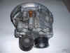
This
is what I started with from an eBay purchase, a used Vortech V1 A-Trim
Super-Charger.
I got it with the Bosch blow-off valve and a misc. items I never
used. The kit was originally for a Chev 350 V8, though this
"basic" supercharger is used in many other applications
as well.
The V1 A-Trim SC has a maximum boost capability of 10
psi depending on pulley diameter used. V5 & V9 models are smaller and produce higher boost and may
be used on a Fiero too. The Z-Spec Super-Charger Kit uses a Vortech V9 (10-20 psi) |
|
|
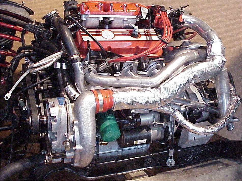
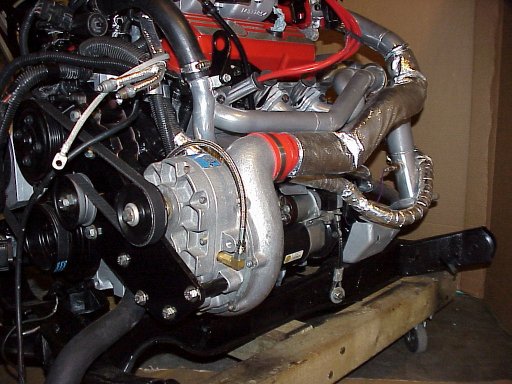
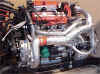
This is the firewall side of the
engine with the Vortech Super-Charger (SC) mounted where the A/C
compressor would be. The 2.75" SC discharge is reduced
with a silicone connector to a 2.25" pipe that runs under the
headers, then up to the throttle body (TB). It is sheathed
in a sleeve sewn from Thermo Tec aluminized heat barrier fabric
(good to 2000 degrees). This is to reduce engine bay heat
from heating up the discharge pipe. The feed pipe from
the fender mounted air filter (not shown) also has a heat
insulating sleeve. |
|
|
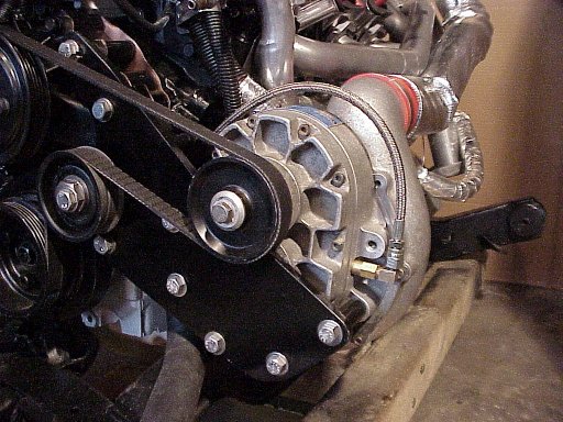
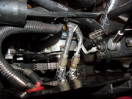
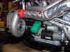
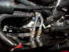
Here's a closeup of the front
corner. A 3/8" thick steel mounting plate was
fabricated that attaches to the front of the engine. It
attaches to two upper water pump bolts and a third mounted
directly into the block near the bottom. Five bolts attach
the SC to the mounting plate. An oil feed line attaches to
the SC to lubricate the gear drive which increase the centrifugal
impeller speed by a ration of 4 times pulley speed. There is
an oil gallery in the block from the oil filter into which the oil
pressure gauge screws into. This gallery has a port above
ths starter, which is where the oil supply line is connected. |
|
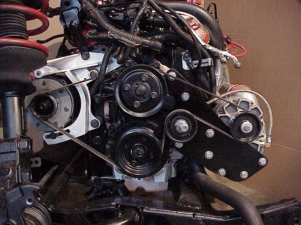
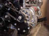
This front shot shows the routing
of the belt drive. We tried to maximize contact on the SC
drive pulley and crank pully to prevent slipage. The pulley
wrap on the alternator is the same as stock. We don't
anticipate any problems with slipage on the water pump, but if
necessary, a second idler pully can be installed between the
alternator and water pump pulley.
|
 |
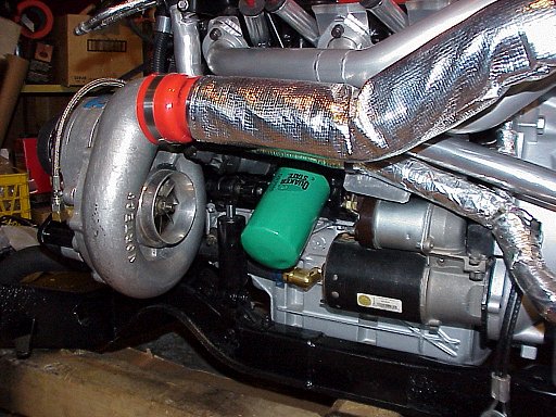
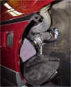
In this photo, it only appears that
the oil filter is in the way. The SC-to-pipe connecter used
will swing up and away from the filter, allowing changing as
normal when doing an oil change. The oil return line from
the SC is visible where in connects to the oil pan. This is
an unpressurized gravity return line, so it must have a slope and
be as large a diameter as possible. We changed the fittings
from 1/2" to the larger 5/8" hose size (the largest that
we could fit to the SC). In the bottom right hand corner,
you can see a torque strap connecting the cradle to the
transmission bellhousing. |
 |
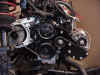
Looking straight down, you can see
the SC fit snugly where the A/C compressor would be. There's
not alot of clearance between the SC housing and firewall (about
3/4"), but the engine has a poly dogbone, all new engine&
transmission mounts, and the secondary torque strap to prevent any
rocking. |
 |
The K&N cone shaped air filter
is mounted in the fender like many other CAI setups Fiero owners
are using. The filter has a 3" connection to the pipe,
which then reduces to 2.5" as it snakes it way past the
exhaust downpipe to the SC. It then increases to fit the
3.5" suction connection of the SC. It is sleeved with a
Thermo Tec fabric sleeve to keep the air cold as it passes through
the engine bay. A rubber mat is fitted and fastened in the
bottom of the area to minimize the amount of dust, water and mud
that normally kicks up into here. This will keep the air
filter cleaner longer as all the intake air will be coming in
through the fender grill. |
 |
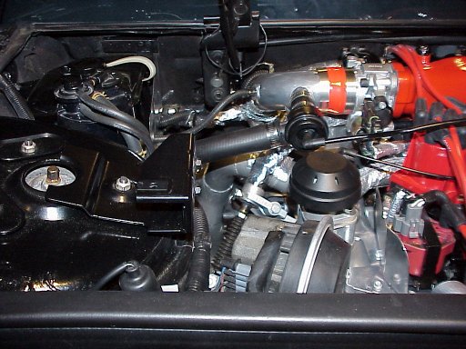
Up top, the intake pipe connects to
the TB with a 2.25" silicone connector. The Bosch
blow-off valve is visible upstream of the TB. It dumps back
into the intake pipe to minimize noise. The water injection
nozzle and MAT (manifold air temperature) sensor are also located
in this area for easy access. In the corner where the stock
air filter would be, is located a tank for the water/methanol
injection system. It is protected from radiant heat coming from the
exhaust downpipe by a heat shield. |
 |
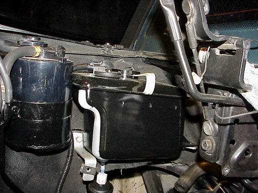
The water/methanol supply tank
(washer tank from a Cadillac Fleetwood) was painted black to be less obvious
in the engine bay, but a strip was left unpainted so water level
can easily be seen. The tank is equipped with a float
switch, and a warning LED is installed in the dash to warn when
the tank's water level is running low. There
are also LEDs to show that there is power to the pump circuit and
when spraying. |
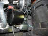 |
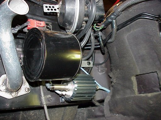
An Aquamist Water Injection system
is installed to cool the air charge and prevent detonation.
The stock cruise control canister was changed to a smaller
one. This allowed space to mount the Aquamist 100 psi water
pump below it. The pump's relay, fuse, and pressure switch
are located here too for easy access. Boost signal for the
pressure switch is taken from the vacuum line to the
canister. The pressure switch is adjustable and activates
the pump when the set pressure is reached. A heat
shield (not shown) protects it from the radiant heat of the nearby
header. |
| |
|
| |
|
| |
|
| |
|
|
|
-Vortech V1 from eBay US$675 (included blow-off
valve and misc.)
-Aquamist Water Injection $650 (complete kit)
-Fabrication of mounting bracket, spacers, & drill/tap of oil
pan $240
-Fabrication of intake tubes (mandrel bends, ceramic coated) $400
-Custom tuned PROM Wester's
Garage $229
-Misc items - belt, oil lines, bolts, turbo-hoses etc.
LINKS:
Vortech Super-Chargers http://www.vortechsuperchargers.com/
I used a V1 A-Trim which has a maximum boost capability of 10 psi.
V5 & V9 models are smaller and produce higher boost and may
be used.
The Z-Spec Super-charger Kit uses a Vortech V9 (10-20 psi)
Aquamist Water Injection http://www.aquamist.co.uk/
Silicone hoses/connectors http://www.turbohoses.com
Thermo Tec
Products http://www.thermotec.com
|
|
|